Stabilizer: designation, description, schemes
Modern man is constantly insurrounded by a huge amount of electrical equipment, both domestic and industrial. It is difficult to imagine our life without electrical appliances, they have imperceptibly penetrated into the houses. Even in our pockets there are always several such devices. All this equipment for its stable operation requires uninterrupted power supply. In fact, jumps of mains voltage and current most often cause the devices to fail.
To ensure high-quality power of technical devices, it is best to use a current stabilizer. It will be able to compensate for the network drops and extend the service life.
The current stabilizer is a device thatautomatically maintains the consumer current with the specified accuracy. It compensates for the frequency of the current surges in the network, the change of load power and the ambient temperature. For example, increasing the power consumed by the device, will change the input current, causing the voltage drop across source resistance and wiring resistance. The greater the value of the internal resistance, the more voltage will change with increasing load current.
The compensation current regulator representsa self-regulating device that contains a negative feedback loop. Stabilization is achieved as a result of changes in the parameters of the regulating element, in the event of a feedback pulse acting on it. This parameter is called the output current function. By the form of regulation, the compensating current stabilizers are: continuous, pulsed and mixed.
Main settings:
1. Stabilization factor based on the value of the input voltage:
TO st.t. = (ΔU in / ΔIH) * (IH / U in), where
IMr. , ΔIMr. - current value and increment of current value in the load.
Coefficient K st.t. is calculated with the load resistance constant.
2. The value of the stabilization factor in the case of a change in resistance:
KRH = (ΔR Mr./ R Mr.) * (IH/ ΔIH) = rі / RH, where
RH, ΔR Mr. - resistance and increment of load resistance;
gi - the value of the internal resistance of the stabilizer.
Coefficient KRH is calculated at a constant input voltage.
3. The value of the temperature coefficient of the stabilizer: γ = ΔI Mr. / Δt okr.
The energy parameters of the stabilizers include the efficiency: η = P out/ P in.
Let us consider some stabilizer schemes.

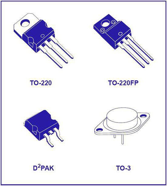
The current stabilizer in the field-effect transistor, with a shorted gate and source, Uin the= 0. The transistor in this circuit is connected in series with the load resistance. The points of intersection of the direct load with the output characteristic of the transistor will determine the current value at the smallest and largest value of the input voltage. When using such a circuit, the load current changes insignificantly with a significant change in the input voltage.

The pulsed current regulator of its distinctivefeature has the work of a transistor-controller in the state of switching. This allows you to increase the efficiency of the device. The pulsed current stabilizer is a kind of a single-cycle converter covered by a negative feedback loop. Such devices, depending on the implementation of the power part, can be divided into two types: with a serial connection of the throttle and the transistor; with series connection of the throttle and parallel connection of the regulating transistor.