VAZ-2110 injector 8 valves: wiring diagram with description
Of great importance is for the VAZ-2110 (injector 8valves) the electric circuit - with its help the whole onboard network is fed. Consumers of different capacities are powered by a battery and a generator (they work in parallel). On the carburetor engines there is no control unit, sensors, electric petrol pump, therefore the wiring is slightly different from that used in the injector structures. But they do have common features.
How is the wiring built?

No matter which engine is usedon the car, the wiring has common features. To understand them, you need to know the basic principles of building electrical. And you need a detailed wiring diagram VAZ-2110 (injector) with a description. Here are the main features:
- All devices and equipment thatconnect to the wiring in cars VAZ-2110, work on a single-wire scheme. All wires differ in color from each other, are responsible for the operation of certain units and assemblies. This greatly facilitates the repair of electrical wiring. And for the manufacturer, this is a significant saving on the wires.
- As a minus wire the car body is used. At VAZ-2110 (injector 8 valves), the electrical circuit is built precisely on this principle.
- The positive conclusion that comes frombattery to consumers, always has a red color. Therefore, when installing the equipment, be sure to use only red wires to connect to the "+" supply. The negative wire always has a black color.
- Each system connected to the electrical equipment is equipped with a wiring harness.
- The electroscheme VAZ-2110 (the injector of 16 valves)is arranged so that when the battery is connected the electrical equipment is energized. It is for this reason that for any repair of the electricians, it is necessary to disconnect the minus terminal.
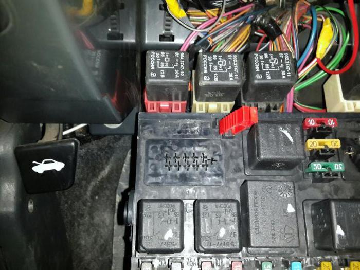
- All circuits are protected by fuses. To switch on powerful power consumers, relays are used.
These features are typical for both carburetor and injector engines. At VAZ-2110 (injector 8 valves), the circuit has exactly such features.
Carburetor engines
The very first VAZ-2110 cars manufactured withmid-nineties, were completed only by engines from the carburetor system of injection. Injection engines began to be installed at the beginning of the two thousandths. They are much better, they work steadily, but still many motorists still use cars with carburetor injection. To date, they are not uncommon.

Significant differences in the electrical circuit betweeninjector and carburetor options are not present. At carburetor "scores" of the system are almost the same as on the injector ones. That's just sure to encounter a problem when replacing the carburetor on the injector. You will additionally lay a few braids of electrical wiring. They are necessary for powering the sensor system, electric petrol pump, on-board computer and other components.
Injection system of injection
For cars VAZ-2110 (injector 8 valves)the electric circuit slightly differs from that used in carburettors. Injection engines are much more complicated, since they have an electronic control unit and a system of sensors, actuators. It is also worth noting that the injector motors are with 8 and 16 valves. There are no carburettor engines with 16 valves. All the wiring can be divided into a boot and saloon.

Their purpose is clear from the title. Podkapotnaya connects elements such as starter, generator, sensors on the engine, etc. Salon wiring is necessary for connecting the dashboard, backlight lamps, various switches.
How to search for malfunctions?
Virtually any failure in the electricalwiring is the first thing to diagnose the contacts. To check their condition, you need to carefully inspect all the wires that are laid in the harness. There are several ways to do this:
- Visual inspection to determine integrity.
- Full inspection of the integrity of the connections, their reliability.
- Prolonka using a multimeter of wires with the battery disconnected.
On carburetor and injector engines, it is necessary to pay attention to wires transmitting a high voltage to the spark plugs.
If they are damaged, the engine will run erratically. Signs of failure of high-voltage wires:
- Extraneous noise when the engine is running.
- The car can jerk while driving.
- Increased consumption of gasoline.
- Unstable operation at low speed.
Therefore, before you sin on any sensors, make sure that the high voltage wires and the ignition module are in good order.
Starter connection
An electric starter is used to start the engine. It is a simple DC motor. The whole system works as follows:
- When the ignition is switched on, the rotor winding of the generator is energized, as a result of which a constant magnetic field is created around it. This is a necessary condition for the operation of the generating set.
- As soon as the key is switched to the "Start" position, the voltage is applied to the retractor winding of the relay.
- Together with the core of the retracting relay, the gear wheel and the overrunning clutch travel along the starter rotor. As a result, the gear engages with the flywheel crown.
- At the same time, the core closes the power contacts inside the retractor relay.
- On the winding of the starter voltage is applied, the rotor starts to rotate and untwists the crankshaft of the engine.
- The generator starts to produce current, since the magnetic field rotates inside the stator winding.
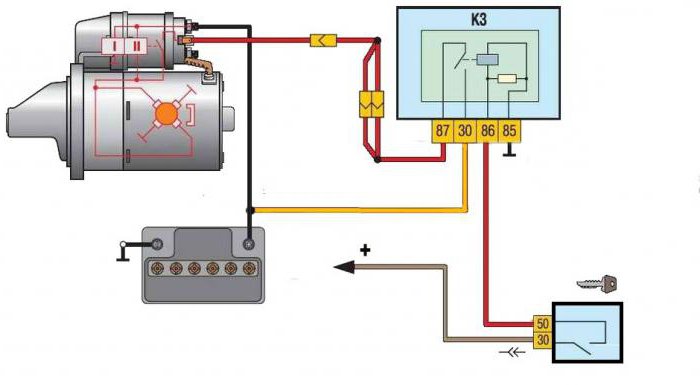
The electroscheme of the starter VAZ-2110 (injector) is the same as in the carburetor models. Only the modification of the starter can differ.
System of heating of salon
The furnace VAZ-2110 consists of a radiator, a fan,duct system. With the help of a fan, the radiator is blown out and air (hot) is fed into special channels. The wiring diagram of the VAZ-2110 heater also includes a damper position adjuster. In fact, this is a conventional stepping motor.
It allows you to move the flap by changing its angleopening, as well as the amount of cold air coming into the heater from the outside. The blower motor is connected via a special switch design. It has several positions, each of which corresponds to a certain rotation speed.

The fan speed is adjusted atThe resistance is installed in the heater housing. These resistances are included in the power circuit of the motor. Switching takes place by means of a regulator mounted on the instrument panel. On older cars of the tenth family, one can still meet mechanical shutter drives. Similar constructions are also found on the "nine" and "eight".
Seat heating system and rear window
These two systems are very similar to each other, because they consist of the same components:
- A fuse for protecting the circuit.
- Electromagnetic relay for switching the power circuit.
- Power button with backlight.
- Wiring harnesses.
- Heating elements.
It is necessary to use electromagnetic relays. They are available in the VAZ-2110 seat heating circuit. With their help, you can get rid of switching with a button of high currents.

As a result, a button on the dashboardonly the low-current control circuits of the windings of the electromagnetic relay are switched. A similar design is also provided for the rear window heater. If the car has heated rear-view mirrors, then a similar scheme is used.
The electric drive of the fuel pump
Through separate fuses and relays occurspower electric fuel pump. It is installed under the rear seat directly in the tank. And it is combined with a gas gauge indicator. The main components of the circuit diagram of the VAZ-2110 pump:
- Electric pump drive motor.
- Electromagnetic relay.
- Fuse.
- Wiring harness.
When the ignition is switched on, the electromagnetic relay responds, and then the fuel pump is energized.

Gasoline is pumped into the system to a certainafter which the electric pump stops. The pressure sensor installed in the fuel rail sends a signal to the electronic control unit. It is for these parameters that the control system understands at what point it is necessary to turn the petrol pump on or off.
Sensors and actuators
In the electrical circuit VAZ-2110 (injector 8 valves)The gasoline pump works on signals coming from the sensors. All these devices are connected to the same control unit. It is with his help that the necessary information on the operation of the internal combustion engine is collected. After processing all signals, the current parameters of the motor are superimposed on the fuel card, which is embedded in the internal memory of the microcontroller.

This fuel card regulates the workactuators depending on the signals coming from the sensors, the load on the engine, the speed of movement, etc. For clarity, you can use the interactive circuitry VAZ-2110 (injector). They allow a much better understanding of the principle of building all the systems of the car.