We carry out the calculation of the transformer
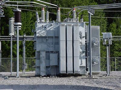
The design of a typical transformer is simple. It consists of a steel core, two coils with a wire winding. One winding is called primary, the second is secondary. The appearance of alternating voltage (U1) and current (I1) in the first coil forms a magnetic flux in its core. It creates an EMF directly in the secondary winding, which does not join the circuit and has an energy force equal to zero.

Transformers are assembled so that the fallthe electrical voltage in the second winding is a small fraction (up to 2 - 5%), which allows us to accept the assumption of equality at its ends of the indicators U2 and EMF. The number of U2 will be more / less as much as the difference between the number of turns of both coils - n2 and n1.
Dependence between the number of wire layersis called the transformation coefficient. It is determined by the formula (and denoted by the letter K), namely: K = n1 / n2 = U1 / U2 = I2 / I1. Often this figure looks like a ratio of two numbers, for example, 1:45, which shows that the number of turns of one of the coils is 45 times less than this one is different. This proportion helps to calculate the current transformer.
Electrotechnical cores produce twotypes: W-shaped, armor, with the branching of the magnetic flux into two parts, and the U-shaped - without separation. To reduce the probable losses, the rod is not made up of solid, but consists of separate thin layers of steel, isolated from each other by paper. The most common is a cylindrical type: a primary winding is superimposed on the frame, then paper balls are mounted, and a secondary layer of wire is wound on top of this.

Calculation of the transformer can cause somecomplexity, but the designer-lover will come to the aid of simplified formulas, which are given below. Preliminary it is necessary to determine levels of voltages and currents forces individually for each coil. The power of each of them is calculated: P2 = I2 * U2; P3 = I3 * U3; P4 = I4 * U4, where P2, P3, P4 - power (W), stacked by windings; I2, I3, I4 - current strengths (A); U2, U3, U4 - the voltage (V).
To establish the total power (P) in calculationtransformer, you must enter the sum of the indices of the individual windings, and then multiply by a factor of 1.25, which takes into account the losses: P = 1.25 (P2 + P3 + P4 + ...). By the way, the value of P will help to calculate the cross section of the core (in sq. Cm): Q = 1.2 * cor.k.P
Then follows the procedure for determining the number of turnsn0 by 1 volt from the formula: n0 = 50 / Q. As a result, the number of coil turns is known. For the first, taking into account the voltage loss in the transformer, it will be: N1 = 0.97 * n0 * U1
For the rest: N2 = 1.3 * n0 * U2; n2 = 1.3 * n0 * U3 ... The diameter of the conductor of any winding can be calculated by the formula: d = 0.7 * cor.kv.1 where I - current strength (A), d - diameter (mm).
Calculation of the transformer allows you to find the current strengthfrom the total power: I1 = P / U1. The size of the plates in the core remains unknown. To find it, you need to calculate the winding area in the core window: Sm = 4 (d1 (square)) * n1 + d2 (sq.) * N2 + d3 (sq.) * N3 + ...), where Sm is the area (in sq. Mm) ), all the windings in the window; d1, d2, d3 and d4 - wire diameters (mm); n1, n2, n3 and n4 are the number of turns. Using this formula describes the unevenness of the winding, the thickness of the insulation of wires, the area occupied by the frame in the lumen of the core window. According to the obtained area size, a special plate size is chosen for the free placement of the coil in its window. And the last thing you need to know is the thickness of the core set (b), which is obtained from the formula: b = (100 * Q) / a, where a is the width of the middle plate (in mm); Q - in sq. M. see The most difficult thing in this method is to perform a transformer calculation (this is a search for a rod element with the appropriate frame size).